

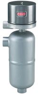
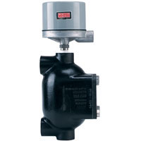
Series 251/253/254 Welded Chamber Level Control
External Mount Pressure to 1250 psig, Hermetically Sealed Switches, Temperature to 750°F, Explosion-Proof Housings
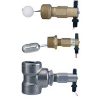
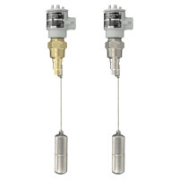
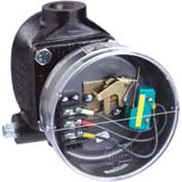
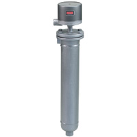
Series 251/253/254 Welded Chamber Level Control, time proven magnetic head leak proof construction combines with a heavy duty welded chamber to provide excellent reliability for control of compatible liquids. Operating pressures of 1250 psig (86 bar) at 650°F (345°C) and 750 psig (52 bar) at 750°F (400°C) are standard. The use of an external magnet reduces the possibility of magnetic particle build up inside the armature tube and subsequent loss of operation as may occur with the internal magnet repulsion design. The controls feature carbon steel bodies and stainless steel internal trim. Process mounting configurations include either side/bottom combination 1" NPT/socket weld hubs, side/bottom flanges or side/side flanges. A variety of hermetically sealed snap action or mercury switches are available in SPST, SPDT, or DPDT action for single or two stage operation. Mercury or Gold alloy snap action contacts are suitable for low current DC applications. A full range of switch enclosures are offered. Many chamber, enclosure and switch combinations are UL approved.
Questions
- Question
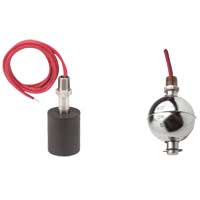
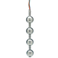
- Why is the minimum specific gravity important on the float level switches?
- Answer
- If a medium has a lower s.g. than the rated minimum for a float, the float will sink through the media and the switch will not operate.
-


_pic.jpg)


Write Your Own Review
| Model | Description | Availability* | Price |
|---|