Series L4 FLOTECT® Float Switch

Series L4 FLOTECT® Float Switch

Series 401 Top Mount Float Type Level Control

Series 401 Top Mount Float Type Level Control

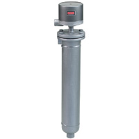
Series 211/213/214 Flanged Chamber Level Control

External Mount, Pressure to 450 psig (31 bar), Temperature to 500°F (260°C)
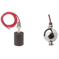
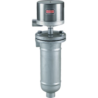
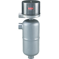
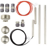
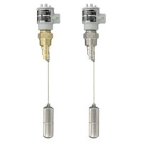
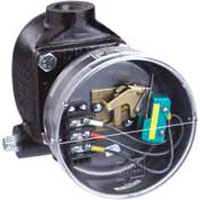
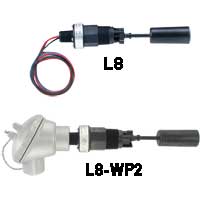
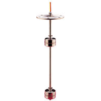
A removable stainless steel float enclosed in a flanged carbon steel chamber is featured in the durable, field proven 211 Series. External side mount series includes 1" NPT process connections as standard, or with socket weld hubs; or, 1" flanges as options. Pressure and temperature limits are 450 psi (31 bar) at 100°F (38°C), and 300 psi (21 bar) at 500°F (260°C). Minimum specific gravity for all models is 0.60. The models shown can be ordered with a variety of electrical arrangements including SPST, SPDT, or DPDT circuits in hermetically sealed snap action or mercury contacts. Switches can be ordered open on level rise or fall. Single pole double throw electrically independent circuits are available as well as low current or high DC current applications. A full range of enclosures are offered including general purpose NEMA 1; weatherproof NEMA 4X; (explosion-proof) and (explosion-proof/vapor-proof) Groups B, C, D, E, F, G, NEMA 7, 9.
Grouped product items
Model Description Availability* Qty Price

Specifications

Minimum Specific Gravity:
0.60
Temperature Limit:
Ambient Temperature: 212°F (100°C); Process Temperature: up to 500°F (260°C).
Switch Type:
Snap or mercury switch. See charts A and B on Model Chart.
Electrical Rating:
See charts A and B on Model Chart.
Wiring Connections:
G, WT or E enclosure, terminal block. EV enclosure, 18" (460 mm) leads.
Process Connections:
1" NPT standard (socket weld hubs or flanges optional). See Model Chart.
Enclosures:
G, painted steel and aluminum. WT, painted steel, aluminum and neoprene. E, aluminum. EV, aluminum and neoprene.
Wetted Parts:
C1 construction. Chamber: carbon steel; Trim: 303SS, 304SS, and 430SS (430SS optional).
Weight:
211: 34 lb (15 kg); 213: 44 lb (20 kg); 214: 51 lb (23 kg).

Product Literature

Manuals

Catalog Pages

Model Chart

    
EXAMPLE 211 2 WT 7810-10 C1 60 L12 211-2-WT-7810-10-C1-60-L12 Level Control, flanged carbon steel chamber, weatherproof enclosure, (2) SPDT snap action switches, lower stage adjustable deadband, upper stage fixed deadband, operating pressure 450 psig @ 100°F, side/bottom 1" NPT process connections, minimum s.g. 0.60.
CONNECTION 211             One Horizontal and One Vertical 1" NPT
213             One Vertical and One Horizontal Flanged Connection
214             Two Vertical Flanged Connections
DEADBAND   1           Single Stage Operation, with Adjustable Deadband
  2           Two Stage Operation, Lower Stage has Adjustable Deadband, Upper Stage has Fixed Deadband
  3           Two Stage Operation, Lower Stage has Fixed Deadband, Upper Stage has Adjustable Deadband
  4           Two Stage Operation, Both Stages have Fixed Deadband with Adjustable Spread Between Stages
ENCLOSURE      G         General Purpose, NEMA 1
    WT         Weatherproof, NEMA 3R, 4, 4X
    E         Explosion-proof, NEMA 7, 9, Class I Groups B, C, D, Class II Groups E, F, G
    EV         Explosion-proof/Vapor-proof, NEMA 7, 9, Class I Groups B, C, D, Class II Groups E, F, G
CIRCUITS
(for electrical circuits
see charts A & B below)
      48XX       Single Stage Mercury Switch, see chart A
      48XX-XX       Two Stage, Mercury Switch, see chart A
      78XX       Single Stage, Snap Switch, see chart B
      78XX-XX       Two Stage, Snap Switch, see chart B
      78XXHM       Hermetically Sealed Snap Switch, see chart B
      98XX       Single Stage, High Capacity DC Snap Switch, use heat fins (HF) if process temperature exceeds 350°F (177°C), do not exceed 450°F (232°C), see chart B
      98XX-XX       Two Stage, High Capacity DC Snap Switch, use heat fins (HF) if process temperature exceeds 350°F (177°C), do not exceed 450°F (232°C), see chart B
CHAMBER MATERIAL         C1     Carbon Steel Body
        C216     316SS Body
        HFC1     Heat Fins & Carbon Steel Body
        HFC216     Heat Fins & 316SS Body (211 only)
MINIMUM
SPECIFIC
GRAVITY
          60   0.60 Specific Gravity (211 only)
          160   0.60 Specific Gravity & 150# Flange (213, 214 only)
          360   0.60 Specific Gravity & 300# Flange (213, 214 only)
          660   0.60 Specific Gravity & 600# Flange (213, 214 only)
OPTIONS             H2 H2 Socket Weld Hub  (211, steel housing only)
            STW SS Tag Wired
            01 Breather Only (E-Housing only)
            02 Drain Only (E-Housing only)
            12 Breather & Drain (E-Housing only)
            23720 Fungus Proofing

CHARTS A & B - ELECTRICAL CIRCUITS AND RATINGS
SWITCH TYPE SWITCH ACTION ELECTRICAL RATINGS IN AMPS ORDERING CODE
AC DC SINGLE STAGE TWO STAGE
120V 240V 440V 30V 125V 250V LOWER UPPER
CHART A
Mercury Contacts
SP-ST open on level FALL 10 5 3†   10 5 -4821 -4821 -21
SP-ST open on level RISE 10 5 3†   10 5 -4820 -4820 -20
SP-DT one switch 4 2 1†   4 2 -4810 -4810 -10
SP-DT two switches E.I.* 10 5 3†   10 5 -4815 -4815 -15
DP-ST two switches E.I.* open on level FALL 10 5 3†   10 5 -4813 -4813 -13
DP-ST two switches E.I.* open on level RISE 10 5 3†   10 5 -4814 -4814 -14
DP-DT two SP-DT switches 4 2 1†   4 2 -4806 -4806 -06
CHART B
snap action contacts
SP-DT one switch 12 5 3†   0.5** 0.25** -7810 -7810 -10
DP-DT two SP-DT switches 12 5 3†   0.5** 0.25** -7806 -7806 -06
SP-DT one hermetically sealed switch 5 5   5**     -7810HM -7810HM -10HM
DP-DT two hermetically sealed SP-DT switches 5 5   5**     -7806HM -7806HM -06HM
DP-DT two SP-DT switches 10 3     10‡ 3‡ -9806 -9806 -06
SP-DT one switch 10 3     10‡ 3‡ -9810 -9810 -10
DP-DT Two SP-DT switches 2 2     0.4** 0.25** -1006 -1006 -06
SP-DT one switch 2 2     0.4** 0.25** -1010 -1010 -10

†Available on special order, change 1st digit in ordering code from 4 to 5 or 7 to 8, i.e., -4820 becomes -5820, -7810 becomes -8810, etc.
‡10 amp inductive (polarized) at 125 VDC.
*Electrically Independent.
**Resistive.

Questions

Question
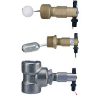
Why is the minimum specific gravity important on the float level switches?
Answer
If a medium has a lower s.g. than the rated minimum for a float, the float will sink through the media and the switch will not operate.
Write Your Own Review
Only registered users can write reviews. Please Sign in or create an account
Model Description Availability* Price